Featured Post

Ultra violet

UV is a form of radiation generated by atomic transitions in chemical reactions such as those present in the Sun and in man-made equipment s...

Wednesday, March 25, 2009

laser

A laser is a device that emits light (electromagnetic radiation) through a process called stimulated emission. The term laser is an acronym for light amplification by stimulated emission of radiation.[1][2] Laser light is usually spatially coherent, which means that the light either is emitted in a narrow, low-divergence beam, or can be converted into one with the help of optical components such as lenses. Typically, lasers are thought of as emitting light with a narrow wavelength spectrum ("monochromatic" light). This is not true of all lasers, however: some emit light with a broad spectrum, while others emit light at multiple distinct wavelengths simultaneously. The coherence of typical laser emission is distinctive. Most other light sources emit incoherent light, which has a phase that varies randomly with time and position.

Terminology
 
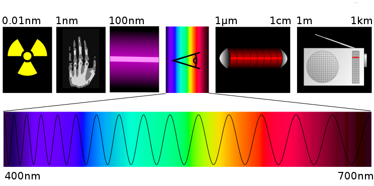
From left to right: gamma rays, X-rays, ultraviolet rays, visible spectrum, infrared, microwaves, radio waves.

The word laser originated as an acronym for light amplification by stimulated emission of radiation. The word light in this phrase is used in the broader sense, referring to electromagnetic radiation of any frequency, not just that in the visible spectrum. Hence there are infrared lasers, ultraviolet lasers, X-ray lasers, etc. Because the microwave equivalent of the laser, the maser, was developed first, devices that emit microwave and radio frequencies are usually called masers. In early literature, particularly from researchers at Bell Telephone Laboratories, the laser was often called the optical maser. This usage has since become uncommon, and as of 1998 even Bell Labs uses the term laser.[3]

The back-formed verb to lase means "to produce laser light" or "to apply laser light to".[4] The word "laser" is sometimes used to describe other non-light technologies. For example, a source of atoms in a coherent state is called an "atom laser".


Principal components:
1. Gain medium
2. Laser pumping energy
3. High reflector
4. Output coupler
5. Laser beam

Tuesday, March 17, 2009

ELINT


Signals intelligence (often contracted to SIGINT) is intelligence-gathering by interception of signals, whether between people (i.e., COMINT or communications intelligence) or between machines (i.e., ELINT or electronic intelligence), or mixtures of the two. As sensitive information is often encrypted, signals intelligence often involves the use of cryptanalysis. However, traffic analysis—the study of who is signalling whom and in what quantity—can often produce valuable information, even when the messages themselves cannot be decrypted. See SIGINT by Alliances, Nations and Industries for the organization of SIGINT activities, and SIGINT Operational Platforms by Nation for current collection systems, and SIGINT in Modern History from World War I to the present.
As a means of collecting intelligence, signals intelligence is a subset of intelligence collection management, which, in turn, is a subset of intelligence cycle management.
Intercepting written but encrypted communications, and extracting information, probably did not wait long after the development of writing. A simple encryption system, for example, is the Caesar cipher. Electronic interception appeared as early as 1900, during the Boer War. The Boers had captured some British radios, and, since the British were the only people transmitting at the time, had signals rather obvious to intercept.[1]
Menwith Hill, a large US SIGINT site in England

Saturday, March 14, 2009

Side lobe


In antenna engineering, side lobes are the lobes of the far field radiation pattern that are not the main beam, where the terms "beam" and "lobe" are synonyms. An antenna radiation pattern is more commonly called a beam pattern. The power density in the side lobes is generally much less than that in the main beam. It is generally desirable to minimize the sidelobe level (SLL), which is measured in decibels relative to the peak of the main beam. The main lobe and side lobes occur for both conditions of transmit, and for receive. The concepts of main and side lobes, aperture shapes, and aperture weighting, apply to problems in radar and optics (two specific applications of electromagnetics) and in sonar.

For a rectangular aperture antenna having a uniform amplitude (or uniform weighting), the first sidelobe is -13.26 dB relative to the peak of the main beam because for such antennas the radiation pattern has a canonical form of

A typical antenna radiation pattern showing sidelobes.

Wavelength


In physics, wavelength is the distance between repeating units of a propagating wave of a given frequency. It is commonly designated by the Greek letter lambda (λ). Examples of wave-like phenomena are light, water waves, and sound waves. The wavelength is related to the frequency by the formula: wavelength = wave speed / frequency. Wavelength is therefore inversely proportional to frequency. Waves with higher frequencies have shorter wavelengths. Lower frequencies have longer wavelengths, assuming the speed of the wave is the same.[1]

In a wave, properties vary with position. For example, in a sound wave the air pressure oscillates, while in light and other electromagnetic radiation the strength of the electric and the magnetic field vary.

Visible light ranges from deep red, roughly 700 nm, to violet, roughly 400 nm (430–750 THz). For other examples, see electromagnetic spectrum. The wavelengths of sound frequencies audible to the human ear (20 Hz–20 kHz) are between approximately 17 m and 17 mm, respectively, assuming a typical speed of sound of about 343 m/s; the wavelengths in audible sound are much longer than those in visible light.
Wavelength of a sine wave.

Radar


Radar is a system that uses electromagnetic waves to identify the range, altitude, direction, or speed of both moving and fixed objects such as aircraft, ships, motor vehicles, weather formations, and terrain. The term RADAR was coined in 1941 as an acronym for radio detection and ranging.[1][2][3] The term has since entered the English language as a standard word, radar, losing the capitalization. Radar was originally called RDF (Radio Direction Finder) in the United Kingdom.

A radar system has a transmitter that emits either microwaves or radio waves that are reflected by the target and detected by a receiver, typically in the same location as the transmitter. Although the signal returned is usually very weak, the signal can be amplified. This enables radar to detect objects at ranges where other emissions, such as sound or visible light, would be too weak to detect. Radar is used in many contexts, including meteorological detection of precipitation, measuring ocean surface waves, air traffic control, police detection of speeding traffic, and by the military.

This long-range radar antenna, known as ALTAIR, is used to detect and track space objects in conjunction with ABM testing at the Ronald Reagan Test Site on the Kwajalein atoll.

Electronic countermeasures


Electronic countermeasures (ECM) are a subsection of electronic warfare which includes any sort of electrical or electronic device designed to trick or deceive radar, sonar, or other detection systems like IR (infrared) and Laser. It may be used both offensively or defensively in any method to deny targeting information to an enemy. The system may make many separate targets appear to the enemy, or make the real target appear to disappear or move about randomly. It is used effectively to protect aircraft from guided missiles. Most air forces use ECM to protect their aircraft from attack. That is also true for military ships and recently on some advanced tanks to fool laser/IR guided missiles. Frequently is coupled with stealth advances so that the ECM system has an easier job. Offensive ECM often takes the form of jamming. Defensive ECM includes using blip enhancement and jamming of missile terminal homers.

Inspecting an AN/ALQ-184 Electronic Attack Pod.

Sonar (originally an acronym for sound navigation and ranging) is a technique that uses sound propagation (usually underwater) to navigate, communicat


Sonar (originally an acronym for sound navigation and ranging) is a technique that uses sound propagation (usually underwater) to navigate, communicate with or detect other vessels. There are two kinds of sonar: active and passive. Sonar may be used as a means of acoustic location and of measurement of the echo characteristics of "targets" in the water. Acoustic location in air was used before the introduction of radar. Sonar may also be used in air for robot navigation, and SODAR (an upward looking in-air sonar) is used for atmospheric investigations. The term sonar is also used for the equipment used to generate and receive the sound. The frequencies used in sonar systems vary from infrasonic to ultrasonic. The study of underwater sound is known as underwater acoustics or sometimes hydroacoustics.

photo: French F70 type frigates (here, La Motte-Picquet) are fitted with VDS (Variable Depth Sonar) type DUBV43 or DUBV43C towed sonars

Sunday, March 8, 2009

VOR


VOR, short for VHF Omni-directional Radio Range, is a type of radio navigation system for aircraft. A VOR ground station broadcasts a VHF radio composite signal including the station's identifier in morse code (and sometimes a voice identifier), and data that allows the airborne receiving equipment to derive a magnetic bearing from the station to the aircraft (direction from the VOR station in relation to the Earth's magnetic North at the time of installation). VOR stations in areas of magnetic compass unreliability are oriented with respect to True North. This line of position is called the "radial" from the VOR. The intersection of two radials from different VOR stations on a chart allows for a "fix" or approximate position of the aircraft.

Developed from earlier Visual-Aural Range (VAR) systems, the VOR was designed to provide 360 courses to and from the station selectable by the pilot. Early vacuum tube transmitters with mechanically-rotated antennas were widely installed in the 1950s, and began to be replaced with fully solid-state units in the early 1960s. They became the major radio navigation system in the 1960s, when they took over from the older radio beacon and four-course (low/medium frequency range) system. Some of the older range stations survived, with the four-course directional features removed, as non-directional low or medium frequency radiobeacons (NDBs).

The VOR's major advantage is that the radio signal provides a reliable line (radial) from the station which can be selected and followed by the pilot. A worldwide land-based network of "air highways", known in the US as Victor Airways (below 18,000 feet) and "jet routes" (at and above 18,000 feet), was set up linking VORs. An aircraft could follow a specific path from station to station by tuning the successive stations on the VOR receiver, and then either following the desired course on a Radio Magnetic Indicator, or setting it on a conventional VOR indicator (shown below) or a Horizontal Situation Indicator (HSI, a more sophisticated version of the VOR indicator) and keeping a course pointer centered on the display.

VORs provide considerably greater accuracy and reliability than NDBs due to a combination of factors in their construction -- specifically, less course bending around terrain features and coastlines, and less interference from thunderstorms. Although VOR transmitters were more expensive to install and maintain, today VOR has almost entirely replaced the low/medium frequency ranges and beacons in civilian aviation, and is now in the process of itself being supplanted by the Global Positioning System (GPS). Because they work in the VHF band, VOR stations rely on "line of sight" -- if the transmitting antenna could not be seen on a perfectly clear day from the receiving antenna, a useful signal cannot be received. This limits VOR (and DME) range to the horizon -- or closer if mountains intervene. This means that an extensive network of stations is needed to provide reasonable coverage along main air routes. The VOR network is a significant cost in operating the current airway system, although the modern solid state transmitting equipment requires much less maintenance than the older units.

photo: D-VOR (Doppler VOR) ground station, co-located with DME.

Identification friend or foe - iff


In telecommunications, identification, friend or foe (IFF) is a cryptographic identification system designed for command and control. It is a system that enables military, and national (civilian-located ATC) interrogation systems to distinguish friendly aircraft, vehicles, or forces, and to determine their bearing and range from the interrogator.

IFF was first developed during World War II. The term is a bit of a misnomer, as IFF can only positively identify friendly targets but not hostile ones. If an IFF interrogation receives no reply, the object can only be treated as suspicious but not as a positively identified foe.

There are many reasons for not replying to IFF by friendly aircraft: battle damage, loss of encryption keys, wrong encryption keys, or equipment failure. Aircraft hugging terrain are very often poor candidates for microwave line-of-sight systems such as the IFF system. Microwaves can't penetrate mountains, and very often atmosphere effects (referred to as anomalous propagation) cause timing, range, and azimuth issues.

more reading http://en.wikipedia.org/wiki/Identification_Friend_or_Foe

photo: An IFF Test Set used for testing transponders on aircraft